Shock-induced beam vibrations
This example is intended as a verification test for the Eulerian-Lagrangian coupling in the VTF. An elastic steel panel is hit by a planar Mach-1.21 shock wave in air. The computation is two-dimensional and the beam simulated by a straightforward one-dimensional implicit finite-difference solver that solves the Euler-Bernoulli beam equation
The load q(x,t) is evaluated on-the-fly as the difference of the hydrodynamic pressures on both sides of the beam. The
BeamELCCoupledSolver-object is an excellent example for the required interface to utilize a given solid mechanics solvers for coupled fluid-structure interaction simulations.
The computations correspond to the simulations in J. Giordano, G. Jourdan, Y. Burtschell, M. Medale, D.E. Zeitoun, L. Houas, Shock wave impacts on deforming panel, an application of fluid-structure interaction. Shock Waves 14 (1-2): 103-110, 2005.
Fluid initial conditions:
| | Verification | Dynamic Impact |
| rhol [kg/m^3] | 1.2 | 1.6458 |
| ul [m/s] | 0.0 | 112.61 |
| pl [kPa] | 200.0 | 156.18 |
| rhor [kg/m^3] | 1.2 | 1.2 |
| ur [m/s] | 0.0 | 0.0 |
| pr [kPa] | 100.0 | 100.0 |
| Location relative to beam | 0.0 | -0.02m |
Numerical simulations
- Two-dimensional Euler equations, air at rest (
 , 100kPa, 293K)
- Hybrid Roe-HLL Riemann solver, MUSCL reconstruction with Minmod limiter, dimensional splitting
- Implicit finite difference 1d beam solver. Steel panel (
 , thickness h=1mm, elastic material behavior with E=220GPa, rectangular geometry with
  .) perpendicular to initial shock front on step, lower boundary clamped, 0.015m behind start of step.
- Source code: [fluid codes] [solid codes]
Fluid-structure interaction verification
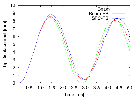
- Apply instantaneous, constant pressure difference of 100kPa along entire beam, no dynamic fluid interaction (Beam)
- Compare tip displacement with FSI simulations for beam solver and plate strip in SFC with initial condition of 100kPa pressure difference, see Shock-induced vibrations of a beam-like panel

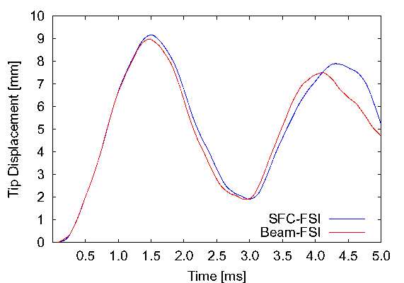
Fluid-structure interaction results with fully dynamic impact
- Fluid domain: 0.4m x 0.08m, AMR base mesh 320x64 cells. Forward facing step geometry with step of 0.015m height and 0.265m length. Reflective boundaries everywhere except left boundary (inflow).
- Compute times on Intel 3.4GHz Xeon dual processors connected with Gigabit Ethernet:
- 2 additional levels with refinement factors 2, 2: 3 fluid CPU + 1 solid CPU = 12.25h CPU
- 2 additional levels with refinement factors 2, 4: 7 fluid CPU + 1 solid CPU = 54h CPU
- Comparison of tip displacement with beam solver and SFC plate strip for beam of 50mm length

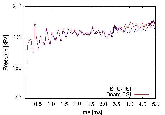
- Tracks of fluid pressure 0.01m before beam at upper boundary. Pressure difference is roughly 100kPa. Beam length 50mm.

- Beam length 50mm, 4763 time steps to t=0.005s. 6.8h wall clock time on 4 nodes of same system as above.
- Beam length 40mm, 4606 time steps to t=0.005s. 6.6h wall clock time on 4 nodes with dual Intel 3.4GHz Xeon EM64T processors connected with Gigabit Ethernet.
--
RalfDeiterding - 12 Jul 2007

 , 100kPa, 293K)
 , thickness h=1mm, elastic material behavior with E=220GPa, rectangular geometry with
  .) perpendicular to initial shock front on step, lower boundary clamped, 0.015m behind start of step.


