Start of topic | Skip to actions
Detonation Front Structure
Problem Description
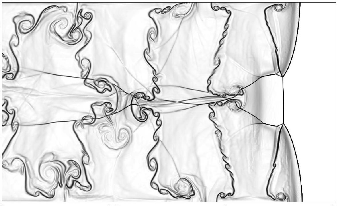
In this study, we performed two-dimensional unsteady simulations of detonation propagation using a five-step simmplified chemistry to examine the qualitative differences in the cellular instability of detonation fronts corresponding to various degrees of competition between the chain-branching and reactive intermediate production. The 2D computation configuration is shown in the folowing.
Numerical Simulation
- Reactive Euler equations in two dimensions (Cartesian coordinate system), using an ideal gas and a five-step, four pseudo species chemical reaction model characterizing hydrogen-oxygen chemistry.
- Time-operator splitting to decouple hydrodynamic transport and chemical reaction
- Explicit second order Godunov-type numerical scheme incorporating a hybrid Roe-solver-based method
- AMR-computation with coarse grid of 600x1000; one additional refinement level, with a refinement factor 3
Initial and Boundary Conditions
- A planar ZND profile was initially placed approximately 10 induction lengths away from the right boundary, and an unreacted hot pocket was placed to the left of the shock in the burned products.
- Cold reactants flow into the domain from the left at a constant velocity
 , hot burnt product flow out of the domain with zero gradient conditions for all flow variables, upper and lower boundaries were no-slip solid walls.
Computational Cases
The physical parameters for two simulation cases which represent regular and irregular shock fronts are listed in the folowing. is the post-shock pressure,
  is the post-shock temperature,
  is the induction zone length (distance between the shock to the maximum temperature gradient) and
  is the reduced effective activation energy.
| Case |  (m/s) (m/s) |  (atm) (atm) |  (K) (K) |  (mm) (mm) |  |
| 1 | 1785 | 30.7 | 2094 | 0.029 | 4.3 |
| 2 | 1390 | 19.5 | 1432 | 0.64 | 10 |
Results
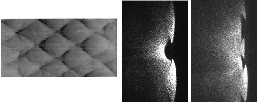
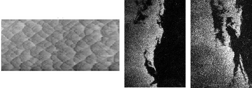
- Numerical smoke foils


- Flow fields (from the left to the right: temperature, mass fraction of reactants, chain radicals, peroxide species)


- Experimental measurements (Pintgen et al 2003, Combustion and Flame)


- For more information please see reference
-- ZheLiang - 21 Aug 2006
| I | Attachment  | Size | Date | Who | Comment |
|---|---|---|---|---|---|
| | XD0.75-y2.mpg | 1400.6 K | 25 Aug 2006 - 21:55 | ZheLiang | Movie of case 1 |
| | XD0.84-y2.mpg | 2478.2 K | 25 Aug 2006 - 21:56 | ZheLiang | Movie of case 2 |
| | two-column.pdf | 2082.1 K | 25 Aug 2006 - 22:45 | ZheLiang | CI Paper |